
How to Connect Computer Wires - Correctly
Computer wiring includes the wires that you see connected to the front of your case, system fans, and miscellaneous motherboard connections. Let's start with the case wires.
| First, identify the different cables that are attached to your case. These are usually bundled together near the bottom, and the computer connectors on the end of the wires are labeled. You will see things like HDD, Power, PWR, etc. Look on your motherboard for the front panel connection area. See label "M" on the mother board diagram.. | 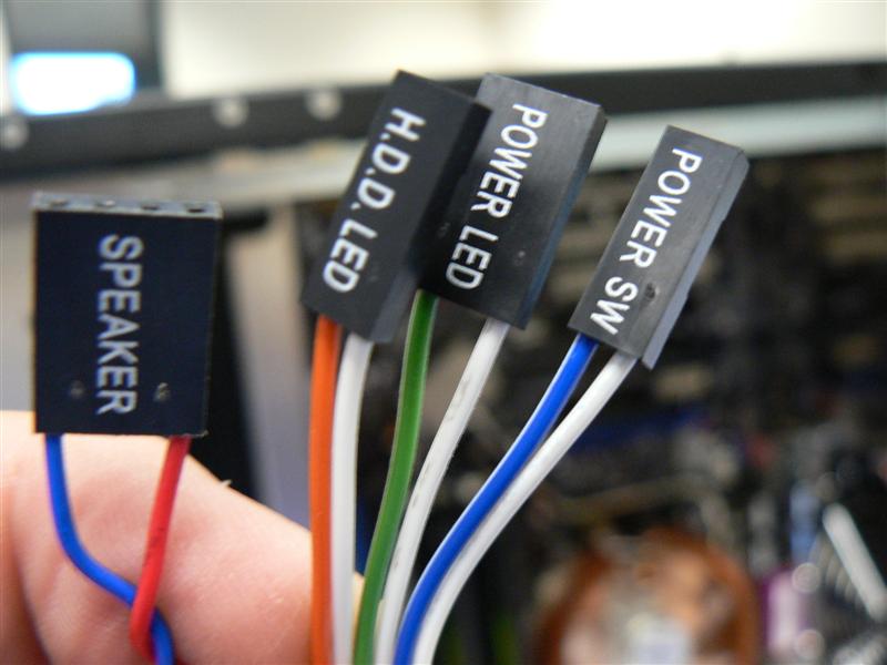 |
| Your motherboard manual will have a page that shows a detailed diagram of what goes where. | 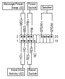 |
Here are the computer connections we need to plug in:
| 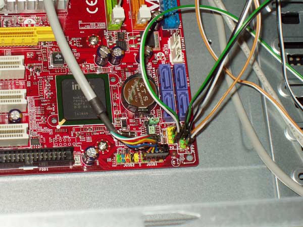 |
Take note of the connection to the left of the all the computer wiring connections. This is the USB connection from the computer case. This is where you will plug in any external USB ports, like the ones on the front of your computer case, or a USB bracket, as shown further down.
All you need to do here is match up each wire with its pin assignments.
I sometimes run into trouble doing the computer wiring, as my fingers have difficulty working with the small connections (as you will see below). A tweezer and flashlight come in handy for this small working space.
Note: You may not use all of the pin connections on the motherboard. This is normal, and not something you should worry about. Case connections differ by manufacturer.
| Let's get the case fans connected here as well. Depending on the case you bought, you can have anywhere from 1 to 4 or more fans in your case. The larger fans that are connected to the case itself will have a small 3 or 4 pin power connection. | 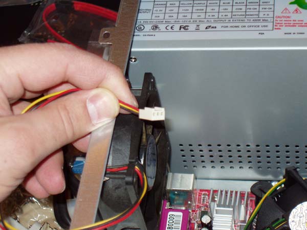 |
| Some cases will have brackets already installed and you simply need to snap the case fans in place. Otherwise, you can use screws that look like this to connect the fan to the case. These screws are inserted from the outside of the case, on the back. | 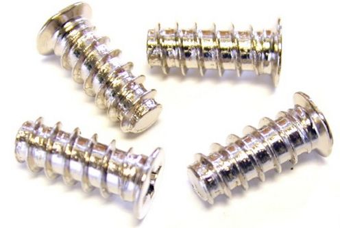 |
These can be connected directly to the motherboard. Find the label that says "sys_fan" and plug it in there. Some fans will come with a 4 pin connector that you will connect directly to the power supply . Then, if you have 2 fans on the back of your case, you can string them together to the same power supply connection, like you would do with Christmas lights. Whenever your computer is on, the fans will be on as well. This also helps to keep the computer wiring neat.

You may have smaller fans in your system. Some computer memory setups come with fans that fit over the top of the memory sticks. If you have one of these, look for a connection on the motherboard that reads something to the effect of "sys_fan" or "sys_fan2". These will be small 4 pin connections that you can plug the smaller fans into.
Using this connection instead of going directly to the power supply will allow your system to control the fan speed dependent on temperature. This will also allow you to control fan speeds once your computer is up and running.
If you have fans on your northbridge or southbridge, you will see computer wiring connections coming from these fans. These will connect into the motherboard directly as well. These are 3 pin connections usually, and will be designed to only fit in a specific plug. These plugs will be very near to the north and south bridges.
These are the most common connections for the case and motherboard. You may have other connections such as chassis intrusion, a trusted platform module, or extra COM and LPT cards that you will need to connect to the motherboard. Please see your motherboard manual for these additional connections.
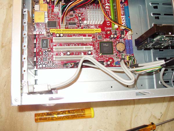
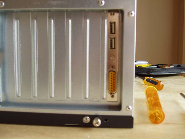
Finally, if your motherboard included an external SATA connection bracket or an external USB bracket, let's hook that in now. Your motherboard may have come with one or the other, or you may have both.

First, connect the bracket to the case. I usually put this on the bottom pci slot to keep it out of the way. You will need to remove one of the metal brackets over the PCI slots on the case.
Connect the SATA cable coming from the bracket to a SATA port on the motherboard. See labels "L" or "N" on the mother board diagram . In this case, position "N" would be used, as it is closest to the bracket.
Connect the power cable from the bracket to an available power connection from the power supply
Connect the USB cable coming from the bracket to the USB port on your motherboard. This will usually be close to the front panel connections that we did earlier. Most motherboards will come with 2 separate USB connections in case you are connecting multiple USB ports. You can use either one for this connection.
If you have a SATA bracket:
If you have a USB Bracket:
Ok, so far so good? You now understand how to wire computer connectors, the importance of wiring harness connectors, and how to correctly connect computer wires?
No comments:
Post a Comment